Adding DSP to an Alinco DX-SR8T HF Transceiver
This is the 3rd HF rig to which I've added a bhi NEDSP1061-KBD digital signal processor (DSP) module, the 1st two being a Yaesu FT-817ND and an Alinco DX70T. I guess that says something about how much I like this mod. It really is like turning SSB into FM - it's that good.


The Alinco DX-SR8T is a great rig for the price: big display, front-firing speaker, simple controls. I got this one lightly used off eBay, with the intent of it being my sons' first HF rig. One of the more interesting things about it is the ability to separate the head and body with a single Ethernet-looking cable. This presents a problem for the DSP install: how to control the DSP functions when the head is separated.

Typically, the "KBD" part of the NEDSP1061-KBD is installed with the switch and LED in the top cover. This would mean the body of the DX-SR8T still needs to be close to the operator.

Additionally, the main board of the DX-SR8T faces the bottom side of the rig, in a cast-aluminum frame. So it means installing the control switch and LED on the BOTTOM of the rig - not ideal at all.
Once I came to the conclusion that I'd have to extend the existing 5 wires between the DSP and control boards, I considered placing the control board on the top side and routing the longer cable to it from the underside. That would put it in the shielded PA / filter section. Again, not ideal.
After thinking about it a bit more, I figured that if I had to break the link between DSP and control boards, why not remote the control board in the head and come up with a quick disconnect, so the head could still be easily removed and extended away from the chassis?
Alinco already came up with a good design, using the 8-pin RJ45 jack we're all familiar with in the form of Ethernet cables. Needing to extend 5 conductors, I chose the RJ12 6-conductor jack readily available. So readily, I had several cables laying around - no need to buy one. Using the 6 pin socket means no confusing it with the existing 8 pin socket. It also means extending the head to chassis distance simply means adding an RJ12 extension cable along with the Alinco remote head kit.
Let's get busy.
First off, a shout-out to Alinco for putting their service manuals online for free. This is one of the reasons I buy their rigs. It's almost as if they are encouraging hacking!

While you might think C386 would be the ideal place to insert the NEDSP1061-KBD, you'd be mistaken. The audio level at this point (as in the DX70T) is too low to process.

R382, a "0 ohm" resistor is the place to install the NEDSP1061-KBD.


It's the green "resistor" right before the LA4425 audio amp IC.

Now let's open the DX-SR8T

You can leave the top cover on if you like. Remove all the case screws on the bottom and the sides, in order to remove the bottom cover.


Looking at it from the rear, the front left corner is where I chose to install the bhi board.
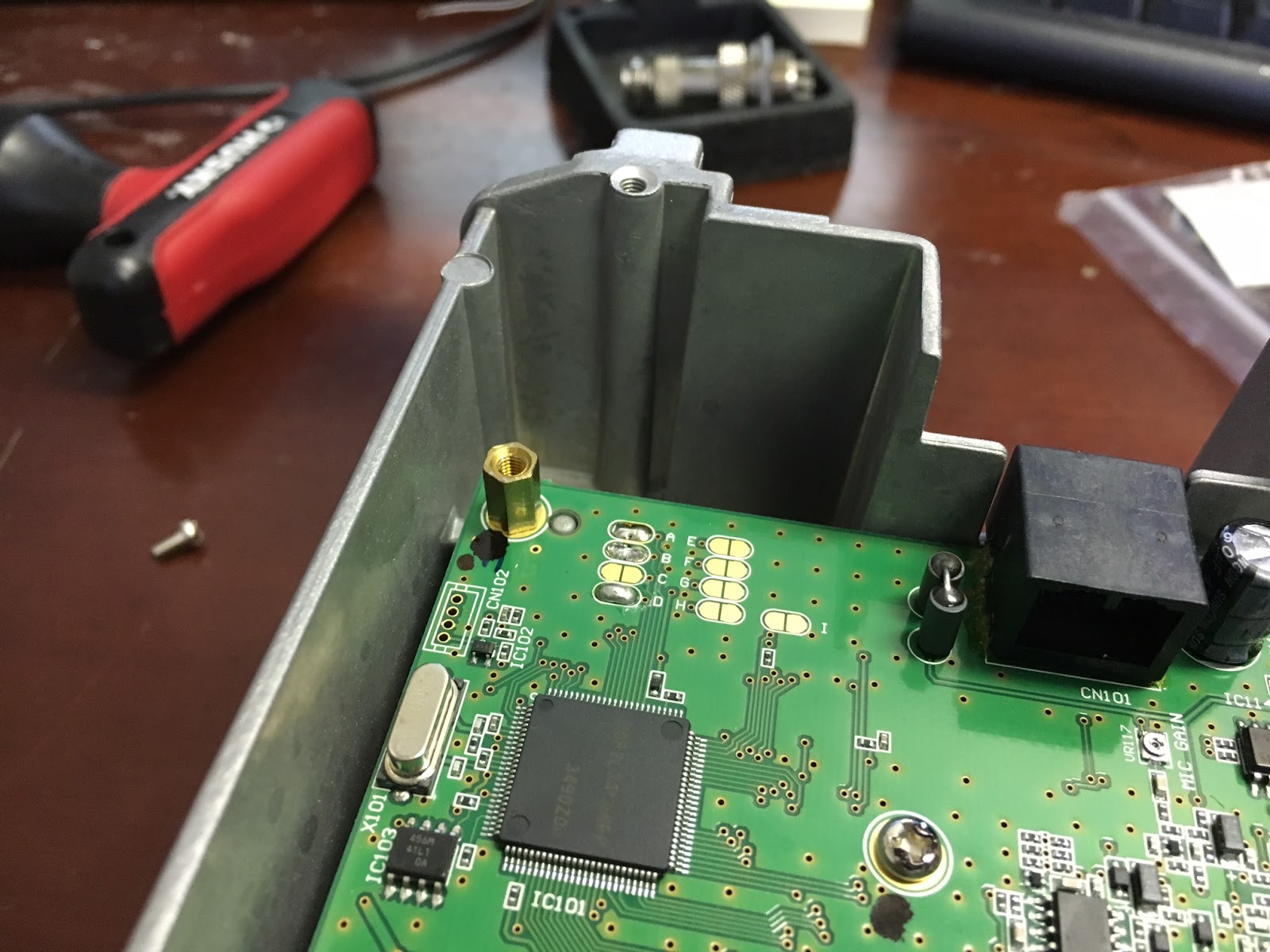
I removed the corner screw and inserted a standard brass standoff from a PC. The original screw then goes back into it.

If you're wondering what those jumper pads are for - they are for modifying stock parameters of the system. Jumpering pad A changes the receive range from 135kHz - 29.99999MHz to 30kHz - 34.99999MHz and jumpering pad B changes the transmit range to 1.6MHz - 29.99999MHz. I'm not sure what the D pad does. I can't find my notes from that. I always "open up" rigs when I can - not to operate illegally, but just to have as much function as is possible: e.g., using the rig as a signal generator into a dummy load for testing another radio.


Just like in the DX70T install, there's a highly convenient 8V test point to which to solder the red power lead.

Note the ground lug screwed to the convenient chassis screw to the left. Note: be sure to trim the red power lead before soldering. You don't want to poke it through too far and ground it on the case below.

The hardest part of this install was securing the audio lead to the pads where the 0 ohm "resistor" was. These SMDs continue to get smaller and smaller. I definitely wanted to use the ground to anchor the audio lead in this case. I chose pin 3 of the audio amp IC. I believe pin 2 also is a ground.

I couldn't get the red and blue leads to solder to the pads with any security, so I tacked them to the neighboring SMDs they are connected to. In the case of the red lead, it is R383. The blue is connected to C389. Just be sure that whatever you tack to is connected directly to the pad you're skipping. I cut a bit of the included insulation for each wire.

Overall what it looks like.

I had pre-coiled the audio lead and tucked it in the convenient free space in front of the bhi board. I debated cutting the audio lead shorter, but I don't think the length savings would reduce noise any noticeable amount. It's shielded. Also, I want to retain the ability to remove the board and install it elsewhere if something catastrophic ever happened to the rig.

Next up is routing the control board to the head unit. Here's the existing RJ45 jack with the bottom in-place. Initially, I'd hoped to glue a jack to the bottom of the RJ45 and cut away the steel cover a bit. But I could not find an RJ12 jack small enough. It could be done, but it would have to extend several mm through the bottom of the cover. A 5 pin small molex type connector could be used, but that connector requires a lot of force to engage & thus I could foresee problems with that solution.

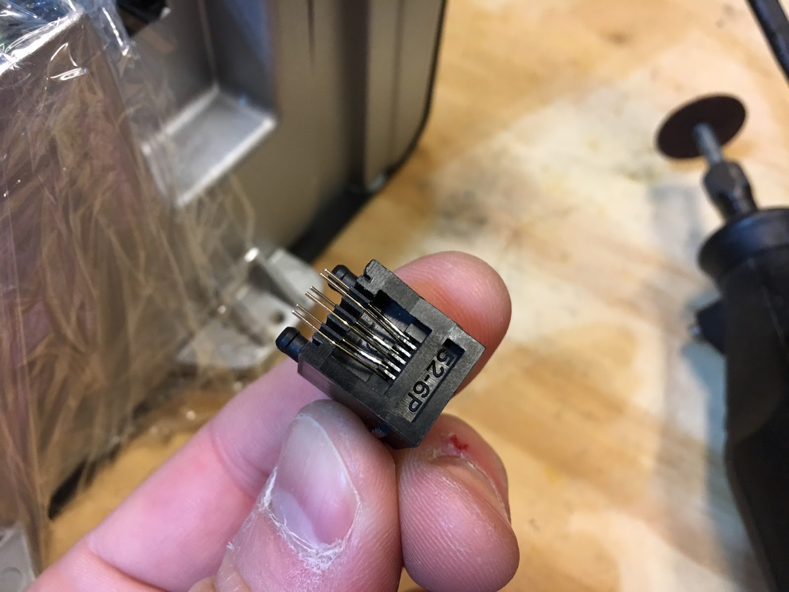
So I wrapped the unit in plastic wrap and put some paper towel behind where I'd cut the aluminum chassis for the RJ12 socket. Again, there's lots of convenient space there. Be careful not to cut the wires behind it. I used a dremel with a small cut off wheel. Be sure to blow out any debris. I found I could wipe off most of it first.

Here's the jack.

And here's the cuts. I found the aluminum brittle enough to make 2 vertical cuts and break off the horizontal with pliers. I then filed it a small bit.


Test fit perfectly.


At this point, you'll cut the 5 wires between the bhi audio board and the switch / LED board. Choose the 5 pins you want to use and solder the 5 wires from the bhi main board directly. Use the insulation included. Be sure to document the connector - what wire goes to what pin! You'll need that to carefully map it to the switch / LED.


Use some hot glue to secure it from the back. I used the ridge on the front of the connector to hold it snug against the chassis.

At this point, you can put the cover back on the main unit, secure all the screws (except the 2 holding the head unit to the chassis).

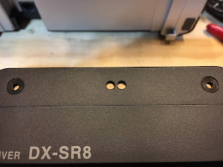
I'd have liked to install the switch and LED in the front face plate of the head, but there is an easy install spot that requires no disassembly.

I pre-placed the board on the rear to figure out where to drill the holes. This spot doesn't interfere with the mounting screws. I also believe it does not interfere with the remote mounting kit (though I don't have one of those to examine).

Now to build the cable. I'd considered installing another RJ12 socket. Then a simple RJ12 straight-through cord could be used. I couldn't find enough space to do that on the head - and I really didn't want to open up the head if I didn't need to do so.

So this is what I built. Snipped 6 inches off one end of a standard RJ12 cord I had already.


Desoldered the existing cut wires from the control board & soldered the RJ12 cord directly to the board. Make sure you follow your custom pinout & color code. Note I've clipped off the red wire here, as that's going to the pin I didn't use.

Hot glue holds the board in-place.


Sticker's in-place and looks OEM. The plastic is thicker than the sheet metal this usually pokes through. It leaves the switch level with the surface, which gives it a slightly indented feel. Still easy to press.

All back together.

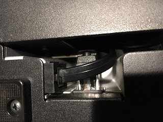
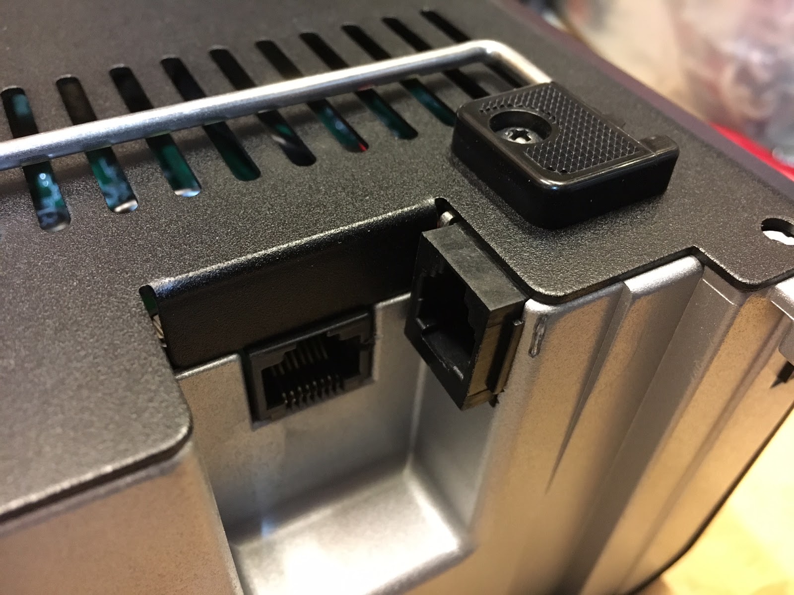
How the connectors look from the underside.
As for setting the levels on the bhi board, I found that the input level had to be set to maximum and the output level backed-off a bit, perhaps set around 75%. Even at max input level, I could not get the overdrive LED to light. If the SMDs weren't so ridiculously small, I would probably play a bit with the values of the resistors to increase the level coming to the bhi board. R383 could probably be replaced with a lower value - or you could try bypassing it. For me, it sounded "good enough" and really, that's what matters with this project.
Video of the finished product:
73, Chris Suleske N7PX


Thanks for this information. I may just have to do this to my Alinco DX-SR8(T). DE WD8WV
ReplyDeleteGood luck! It's a worthwhile mod for sure. I need to put the rig on the bench and adjust the input volume on the DSP board a bit. It's a tad low - that is, the speaker should be putting out more volume.
Delete